Two quotations can both say “3-inch Class 150 ball valve” and list the same 203 mm connection length. Yet the catalogue passage can be 76 mm in one option and 51 mm in the other. Before comparing prices, the buyer needs to confirm which passage each supplier is offering.
The following comparison uses published ZGV trunnion-mounted ball-valve dimensions. It shows what a buyer can establish from the catalogue, what requires a flow calculation and which questions belong in the enquiry.
1. Read the passage dimension, not just the nominal size
Full bore and reduced bore describe the internal passage. They do not establish pressure rating, flow coefficient or suitability for a particular fluid. Ask for the actual minimum bore and the applicable product-standard requirement rather than accepting the word “full” as a dimension.
ZGV’s reduced-bore table uses size descriptions such as 3×2×3. That entry has 3-inch ends and separately lists d = 51 mm and D = 76 mm. Retain both drawing letters with their values: a quotation that reports only “76 mm” leaves out the smaller passage that matters to this comparison.
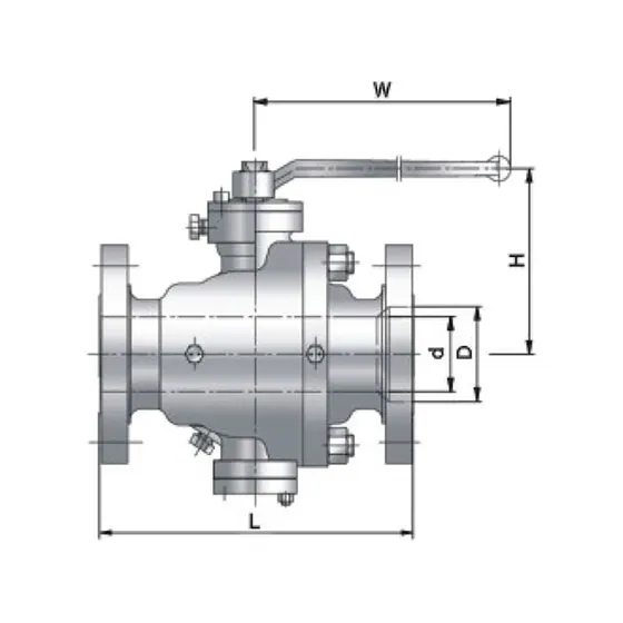
Figure 1. ZGV reference 2514 catalogue drawing. Keep the dimension letters attached to the quoted values; use an approved drawing for the offered assembly.
2. Compare entries within the same pressure class
The Class 150 entries below come from the ZGV Class 150/300 trunnion ball-valve tables. The Class 600 entries come from the Class 600/900 catalogue tables. These are published catalogue values, not measurements of delivered valves.
| Catalogue configuration | Listed passage, mm | Length L, mm | Height H, mm | Listed weight, kg |
|---|---|---|---|---|
| Class 150 NPS 3 full bore | D 76 | 203 | 193 | 33 |
| Class 150 3×2×3 reduced bore | d 51 | 203 | 165 | 30 |
| Class 600 NPS 3 full bore | D 76 | 356 | 247 | 50 |
| Class 600 3×2×3 reduced bore | d 51 | 356 | 176 | 41 |
L and H retain their catalogue drawing labels. H is not the complete assembly height. The listed operator dimensions also differ, so the rows compare catalogue configurations rather than the isolated effect of bore diameter. Confirm the operator arrangement and the scope included in each listed weight.
Within each class, the two entries share L while their passages, H dimensions and listed weights differ. The Class 150 reduced-bore entry is 3 kg lighter than the 33 kg full-bore entry, a calculated reduction of 9.1% against that full-bore entry. The Class 600 difference is 9 kg against 50 kg, or 18.0%. These are comparisons of the listed catalogue weights. They do not establish a price discount or a weight reduction for a complete automated package.
3. Use area and velocity calculations for the question they answer
For a circular passage, area A = πd²/4. Applying that calculation to 76 mm and 51 mm gives the following comparison. The last row assumes the same incompressible liquid flow of 30 m³/h through each section and uses mean velocity v = Q/A.
| Calculation | 76 mm passage | 51 mm passage |
|---|---|---|
| Circular area | approximately 4,536 mm² | approximately 2,043 mm² |
| Area ratio (76 mm passage = 1) | 1.000 (reference) | approximately 0.450 |
| Mean velocity at an assumed liquid flow of 30 m³/h | approximately 1.84 m/s | approximately 4.08 m/s |
The 30 m³/h flow is an illustrative assumption, not a ZGV capacity rating or flow test. The calculation concerns the two circular sections and does not model the complete valve or other restrictions.
At that assumed flow, the 51 mm section has about 2.22 times the mean velocity. Its 45.0% area ratio does not mean 45.0% of the flow capacity, 2.22 times the pressure drop or a specified energy penalty. The complete internal shape and the service conditions must enter a pressure-loss assessment.
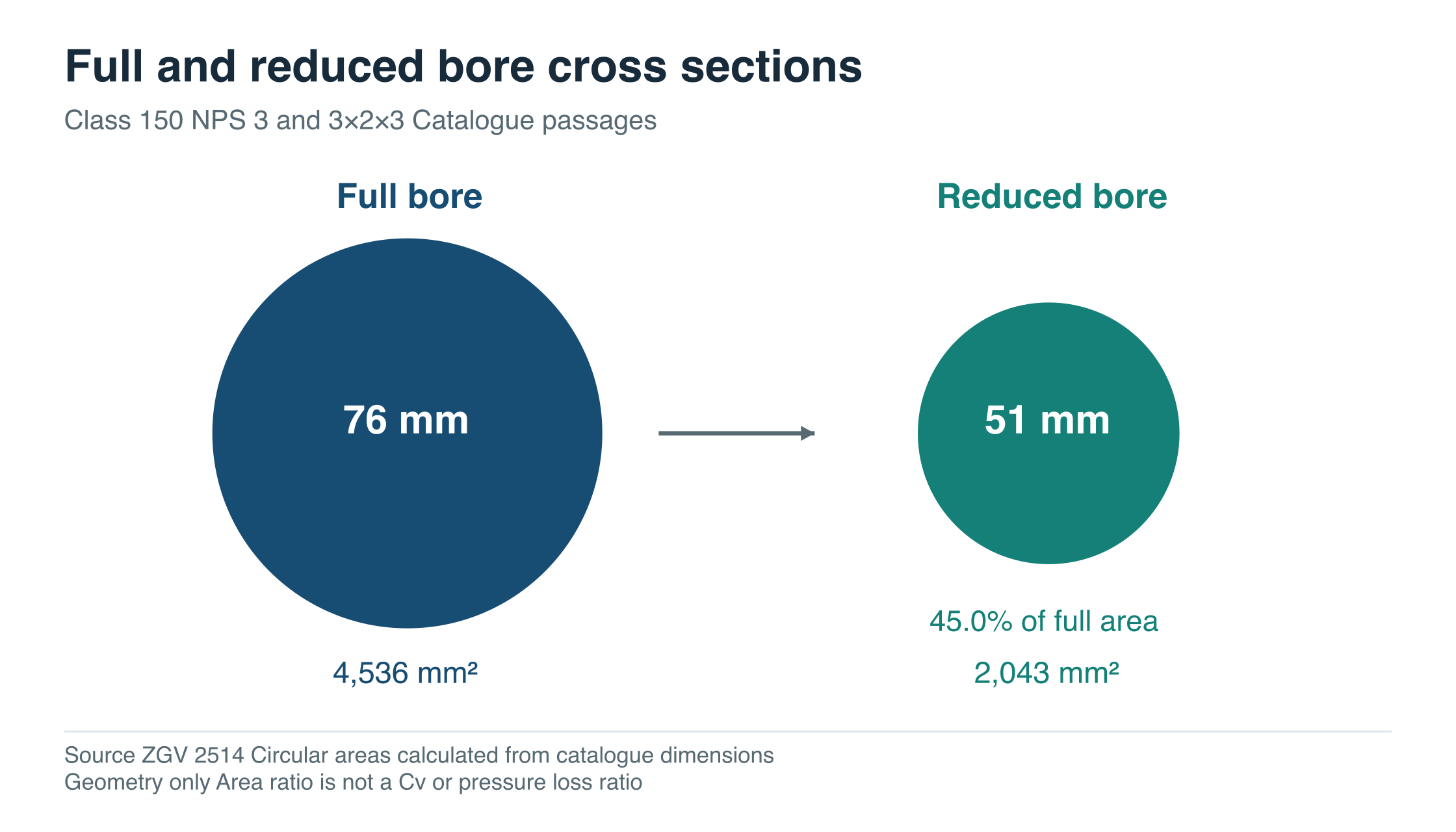
Figure 2. Circular-area comparison using ZGV reference 2514 dimensions. The geometric ratio is not a Cv or pressure-loss ratio.
4. Check the selected size before applying a percentage
“Reduced bore” does not describe one fixed percentage reduction across a product family. Three Class 150 pairs in the same ZGV reference 2514 tables show why.
| Class 150 nominal end size | Full bore D, mm | Reduced bore d, mm | Reduced area / full area |
|---|---|---|---|
| NPS 3 | 76 | 51 | 45.0% |
| NPS 4 | 102 | 76 | 55.5% |
| NPS 6 | 152 | 102 | 45.0% |
Source: reference 2514 full- and reduced-bore tables. Area ratios are calculated from the listed circular passage diameters and rounded to one decimal place.
The NPS 4 pair retains a different area proportion from the NPS 3 pair. Use the actual offered dimensions whenever size or configuration changes. A flow coefficient borrowed from another valve size or design does not settle the comparison.
5. Review pressure loss, cleaning and installation separately
For a liquid duty, request configuration-specific Cv or Kv and a calculation at the relevant flow, pressure and temperature conditions. Gas, steam, flashing liquid and two-phase service require appropriate sizing treatment; the simple liquid velocity example above cannot be extended to them.
Where a cleaning pig or inspection tool must pass, obtain the complete passage and transition drawing and check it against the specified tool and pipe inside diameter. A full-bore label alone does not confirm piggability. Where solids or deposits occur, identify their size, concentration and behaviour, together with the operating sequence.
For a replacement valve, verify flange facing, drilling, pipe schedule, end transitions and operator space as well as length. A lever, gearbox or actuator can change the required envelope. Ask the supplier to show the lever sweep or actuator envelope on the assembly drawing in the intended installation orientation. Matching L alone does not approve the replacement.
6. Make both suppliers answer the same enquiry
| Buying requirement | Evidence to request with each quotation |
|---|---|
| Required passage | Minimum bore, drawing labels and the applicable product-standard requirement |
| Pressure loss at operating flow | Configuration-specific Cv or Kv and a calculation for the stated fluid conditions |
| Cleaning or inspection tool passage | Complete passage and transition drawing checked against the specified tool |
| Fit in existing pipework | Connection details, approved length and complete operator envelope |
| Delivered scope and cost | Materials, operator, inspection documents, included items, exclusions and delivery basis |
State full or reduced bore explicitly, with the required minimum passage. Attach the fluid conditions, flow range, allowable pressure loss and any cleaning-tool specification. An enquiry line can read: “NPS 3, Class 150; state full or reduced bore and the minimum passage in mm; attach the dimensional drawing and Cv or Kv for the offered configuration.” Add the required materials, operator and inspection scope before asking for a firm price. Record each missing answer as a quotation deviation with an owner and a resolution date.
A reduced-bore option can be reasonable when the process assessment and project requirements support it. Full bore may be justified where passage or allowable loss is a binding requirement. Compare price after those requirements and the delivered scope have been aligned.
The complete ZGV full-bore and reduced-bore comparison links the source tables and the valve RFQ worksheet for preparing an enquiry.
Catalogue data reviewed on 17 October 2026. Website reference numbers identify published entries, not the final engineering model. Confirm current drawings, pressure-temperature limits, materials, flow data and commercial scope for the actual offer.